How the gauge design works
To make things clear about the second ball it is there only to provide a stable platform in a straight line to the reference point ball inside the bore for the gauge to operate correctly, it is also there to prevent rocking because there is no need to hold the gauge once you have inserted it in the barrel this in turn eliminates hand tremble and hold errors because the gauge relies ONLY on gravity to affect a stable reading and its inherent weight also pulls the gauge to the lowest point on the barrels internal curve. The stabilizer/ bearing plays no direct role in measurement at all because all measurements are made strictly between the measuring point ball which is held firmly against the barrels internal surface by gravity acting on the total weight of the gauge, and the measuring ball is the only point directly in line with the dial gauge plunger. Now the distance between the balls is four inches and was found to be the ideal distance by trial and error over many years, less than four inches enabled the gauge to rock easily. Extending the distance between the balls meant that you also needed to extend the gauge�s length and by doing so you started to increase flexing errors If you kept the gauge length the same and still extended the distance between the balls on long chamber guns the stabilizer/bearing could end up positioned in the guns chamber and making a true reading impossible. If you put the gauge into a barrel at this point it will come to rest on the stabilizer/bearing and limb rather than the measuring point and stabilizer/guide bearing purely because of the gauges combined weight past the stabilizing/ bearing balance point thus causing the gauge to act in this manner. This is caused today by the lack of weight and mass of the dial gauge, when I first started this project dial gauge bodies where made from a brass casting weighing in at around 7 ounces which was more than enough to pull the reference point ball into contact with the surface. But today modern dial gauges are made from aluminium and weighing about half the weight of their predecessors, if you feel that you are putting to much weight on the dial gauge you can fit screw on extra weights either side of the external limb by the dial gauge clamp joint especially if you want to use a digital dial gauge. I have also included my very first dial gauge in the completed gauge photograph because it was in at the start of this project though it is now not functioning correctly because of the large amount of internal ware it sustained over some forty years of nearly use and it is now one of my keep for life objects because it was a workshop slave when I was.
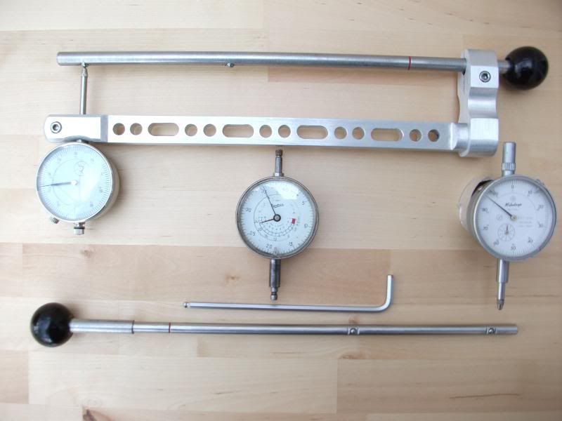
There is a sound reason why I have not included the additional weight in the gauges physical construction to bring the correct balance which is I use different dial gauges in conjunction with the gauge also the gauge�s basic design is so right. One gives Imperial measurement and the other is Metric neither dial gauge weighs the same (the Baty fitted in the gauge weighs 3.5oz and the Mitutoyo weighs 5.5oz) weight or has the same physical dimensions they are manufactured by two different makers this also accounts for the extra shaping of the external limb under the base of dial gauge, so to keep things simple it is far easier to add weight to the dial gauge making replacement far simpler this also makes good sense because it is the only part of the wall thickness gauge liable to break down in some way. Finally talking about dial gauges you could spend a lot of cash and purchase a digital dial gauge but I personally have reservations about them, they seem to weigh next to nothing and are blown of the bench when you sneeze though it also may be just bad luck on my part but my experience of one is that when I need the �D###� thing the battery is flat or when I eventually get around to using it the battery starts to fail so you pays your money and takes your chance it is your decision. To calculate the weight needed to hold the gauges measuring point ball firmly in contact with the barrel�s internal surface the manufactures of dial gauges kindly put a convenient mounting point for the required weight that is always in direct line with the plunger on the back of the gauge. Tie a piece of cotton to the mounting point with a bolt fixed to the other end then add nuts until the gauge comes rest on to the zero point and in doing so the gauge will now be sitting on both zero and stabilizer/bearing points, weigh the bolt and all the nuts then add a minimum of fifty percent more weight and adjust a separate piece of metal to this combined weight and fix to the back of the dial gauge, I like to use silicon rubber it holds well and you can remove the weight from the gauge quite easily. By adding weight to the external limb this also preloads the limb inside the barrel and in doing so reduces further the amount it can flex inside the barrel this is lost important to the .410 version because of its slender design. The lesson all those years ago in the workshop with sitting on the �I� beam was not wasted at all!!!!!!!!!!!!!!!!!
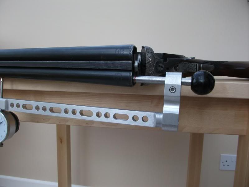
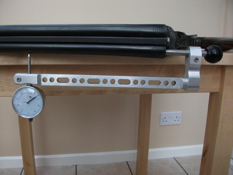
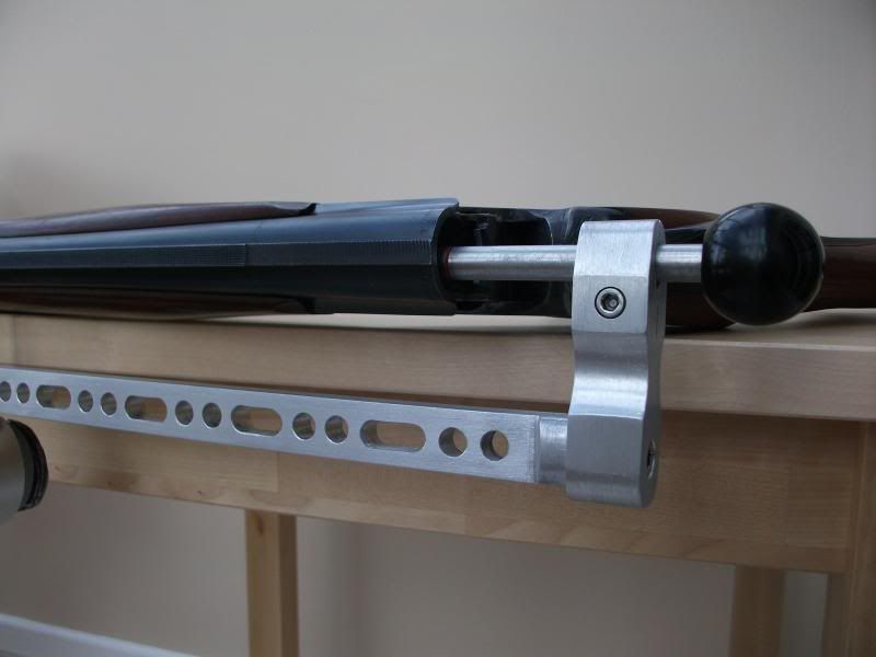
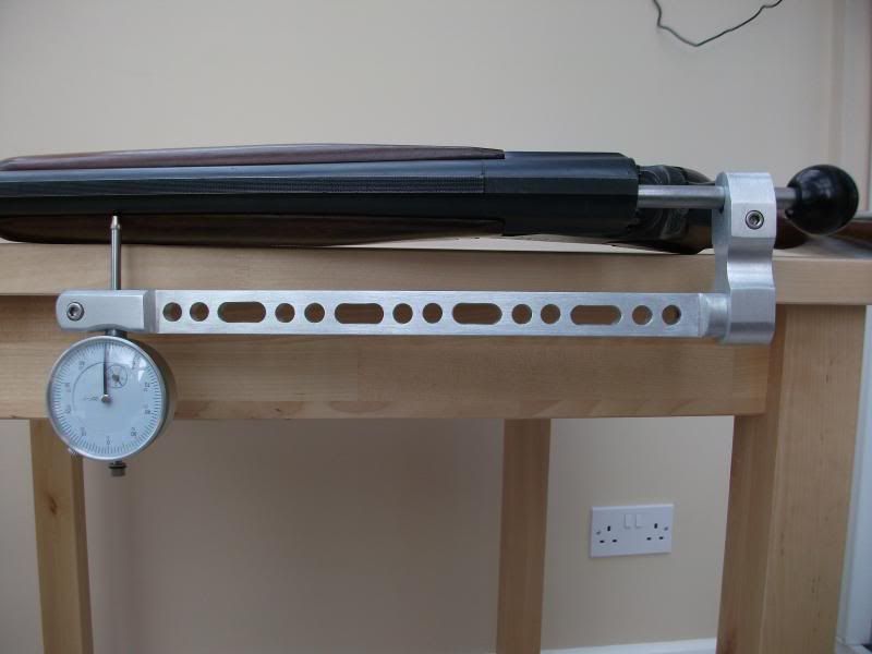
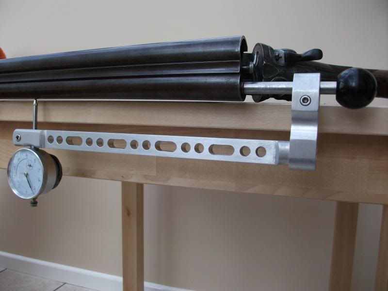
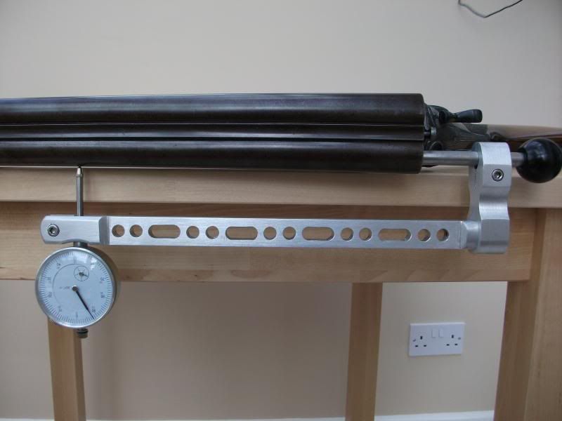
I thought at this point I should post some photographs of the gauge in use. Please note the guns are all complete and not striped down and the Gauge enters without a problem on the �side by side, side by side hammer, and the over and under,� though they are all 12 bores in the pictures though I am sure that you can see the way the gauge hangs differing bore sizes will make no difference to the gauges functionality.
My last posting will be how to zero the gauge but I do feel sure if you have made it this far that you will have guessed by now the how and the why.


