doublegunshop.com - home
Posted By: damascus Make it at home barrel wall thickness gauge - 03/16/13 04:18 PM
Measure me


A very simple exercise if you have the right equipment but almost impossible if you don’t so I would now like to take you back now to the 1960s. At this time here in Britland there was no requirement for a licence to own a shotgun in fact you could buy shotguns mail order and from other general outlets, how things have changed here. So unless you purchased a gun new deciding how healthy it was in the barrel department was as difficult then as it is today if you are unable to take a true measurement of the barrels wall thickness. A bargain gun is not a bargain if the barrels are made thin by excessive bore lapping (honing) and polishing in the attempt to remove pitting this type of fix still traps the unwary regularly today. At this time there where a large number of second user guns around especially in rural areas but you really needed to know how to separate the honest gun from one made to look the part for a quick sale. The most popular bore sizes where the ubiquitous 12 bore the .410, 16, though 20 bores seemed far less common than they are today. After I made a couple of rather disastrous gun acquisitions at Auctions I decided I had to do something in order to improve my chances of purchasing sound examples of the gun maker’s art, so some form of measuring device was required. Being a young engineer just starting out in life I did know what was needed but had little spare cash to purchase the extremely expensive ready made items that would probably only see use two or three times a year, any way my money was taken up by the more important things in a young mans life, guns, cartridges, beer, oh! And the opposite sex!
Now before we start there is few things that should be understood when I first started to make this thickness gauge knowing no better my first design was two bars fitted in to a block of hard wood complete with a Micrometer head at one end it looked the part but it was totally useless and not because of the wood.
It was so unstable when it came to that all important zeroing and use it was just not readable at all because of your hand movements. After this not so auspicious start I had a talk to one of the old time engineers in the workshop and he gave me a demonstration that I have never forgotten from that day to this. Along the back of our workshop where a stack of 12 x 9 inch universal steel “I” beams with one of the beams sticking out of the pile to a distance of about five feet. Now I could see I was in for a lesson when he said “go fetch a drop clock” (A drop clock is the old engineers name for a Dial Gauge) he put the Dial Gauge between the floor and the bottom end of the beam and sat on the beam and to my surprise there was a deflection showing on the gauge. Now I should say that he was a rather rotund gentleman but there was at least three tons of steel holding the beam down at the other end so it could only be him who was causing the deflection on the dial. That was the lesson!!! I could make the limbs of the gauge so thick as to make it impractical to use but it would not stop deflection.
I did not come up with a perfect design right away it sort of evolved over time, there where many attempts but I had one stipulation that never changed whatever design I came up with it had to cost next to nothing, with no use of specialised tools in their making and what ever the design was it must be made at home on the kitchen table. To make something on the kitchen table is sort of a Brit saying, most people do not have a well equipped workshop and the only bench they have is “the kitchen table” and a lot of fine things over the years have been produced in this way.
The starting point was what ever idea I came up with it had to be easy to use, infinitely adjustable to make up for inaccuracies in its make up, small as practicable, and must be able to measure shotgun barrel at the standard UK proof distance of nine inches from the breech face. The accuracy had to be good enough to tell if the gun was worth buying, so with trial and error over a long period of time the eventual design I came up with makes the Gauge compact in size stable in use light to carry, and this aspect puts my personal stamp on its inception and eventual final design. Even though the design is my property I am quite happy for any individual to manufacture one of these gauges for their own personal use, though I am quite sure prior use and intellectual property would come in to the equation if a production for profit enterprise where started, though we could always talk about it if someone wanted to give it a try.
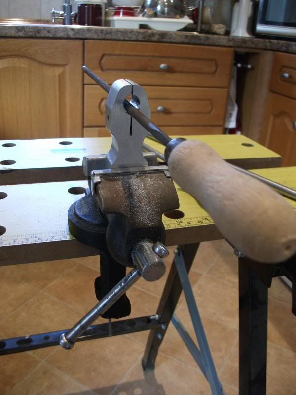
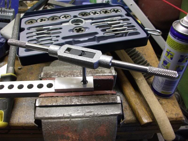
The gauge in this article I made very recently by hand using new materials, I do have a well equipped workshop with all the machine tools needed to manufacture it in less than an hour, though to make it by hand using a drill press a selection of files thread taps and a small table vice and not forgetting the hack saw, did take considerably longer as you would expect. All steel and aluminium I used was purchased via e-bay as was the Dial Gauge and knobs. I can appreciate that not every body has the capability of producing great things with their hands, but still this may be worth a try because it is not as complicated to make as it may first appear plus the monetary sums involved are not that large compared to what you will have in the end. As an apprentice engineer back in my now dim past I was for ever being told when things did not go according to plan or disastrously wrong “A man who never makes a mistake never makes anything” I can assure you that no truer word has ever been spoken. Though just for political correctness I suppose it now should be “person rather than Man”


How it all works

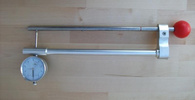
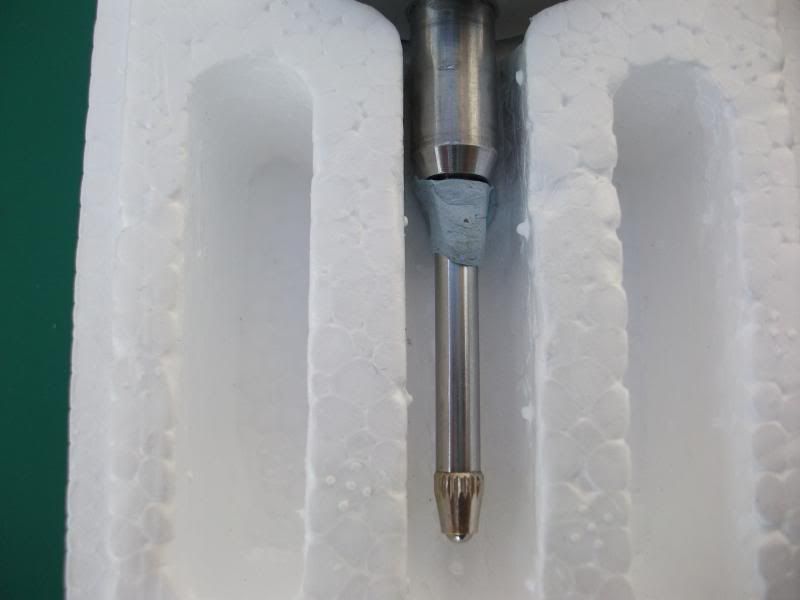
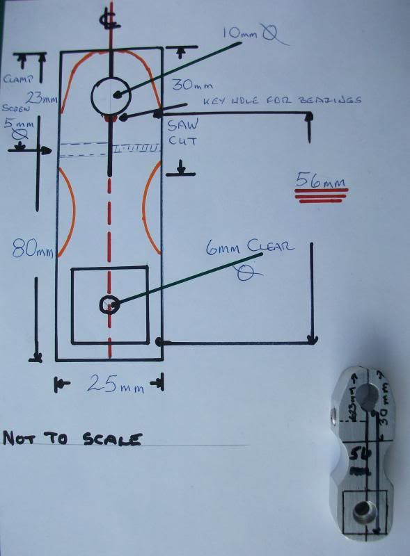
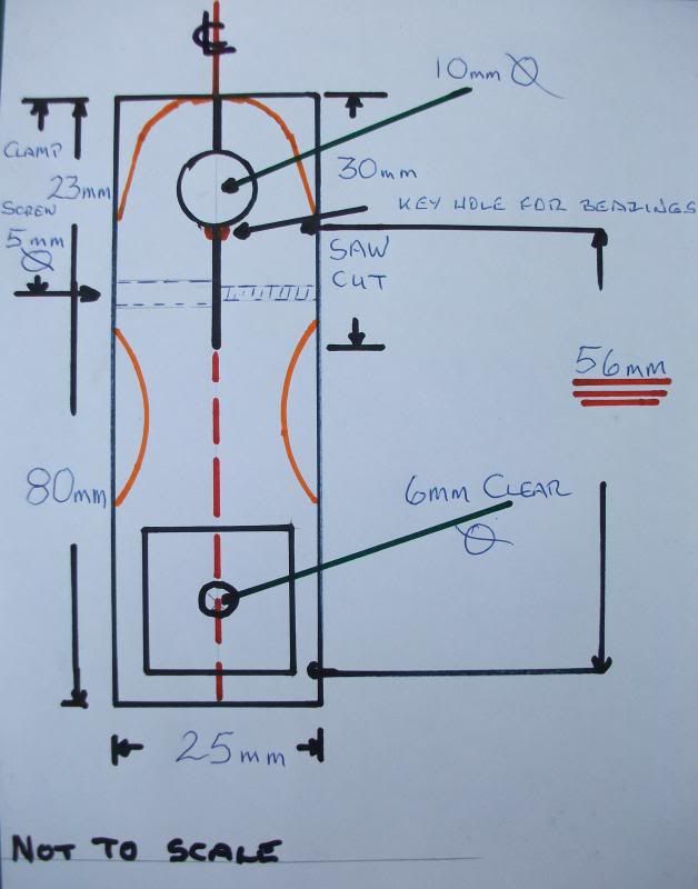
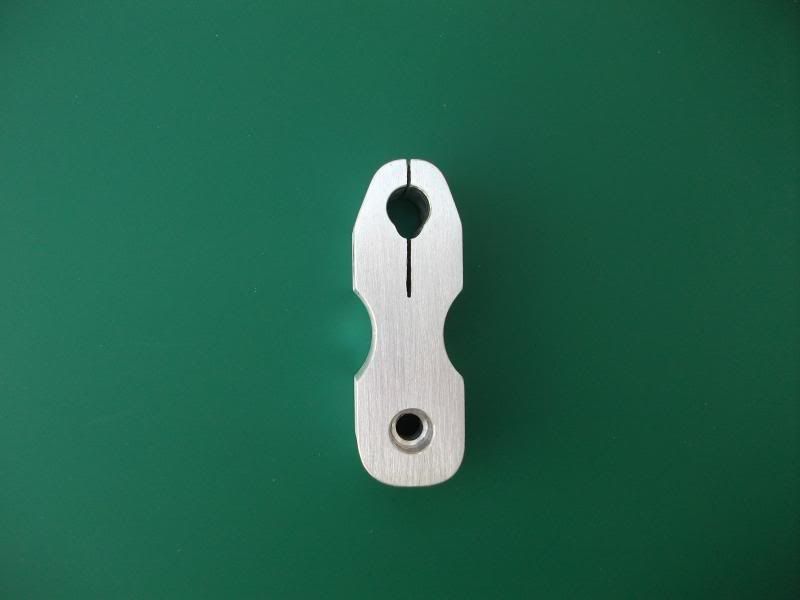
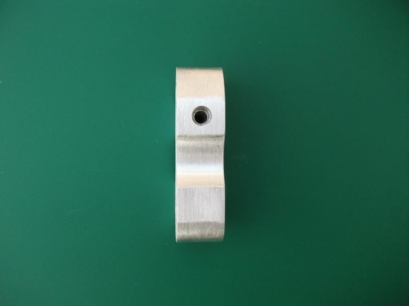
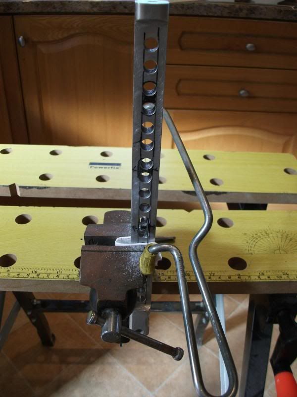
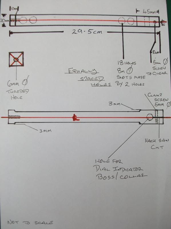
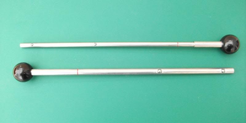
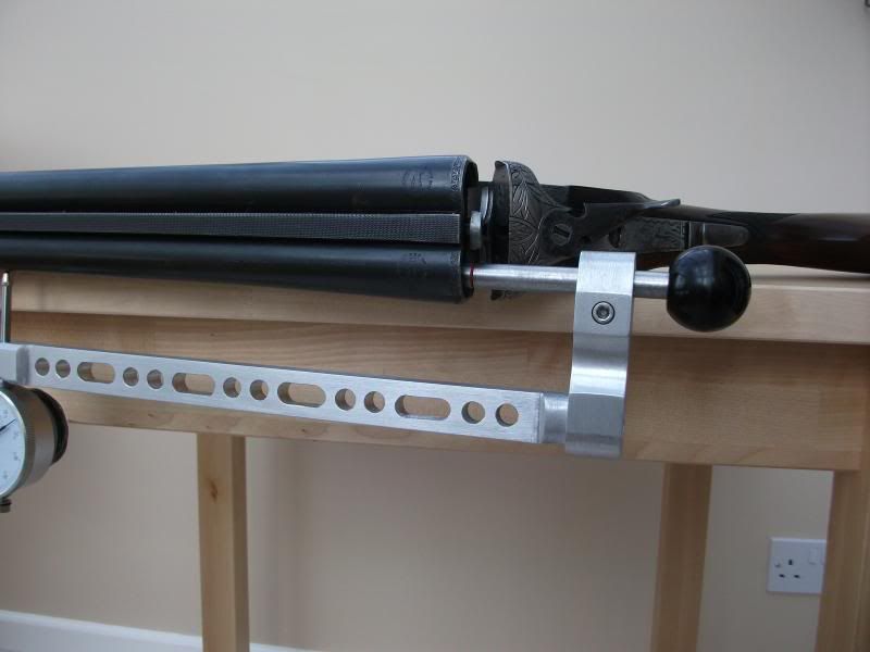
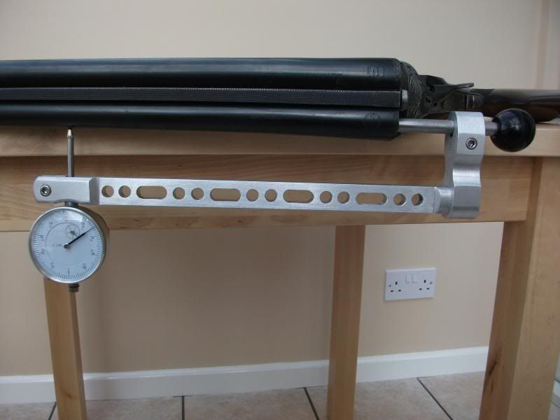
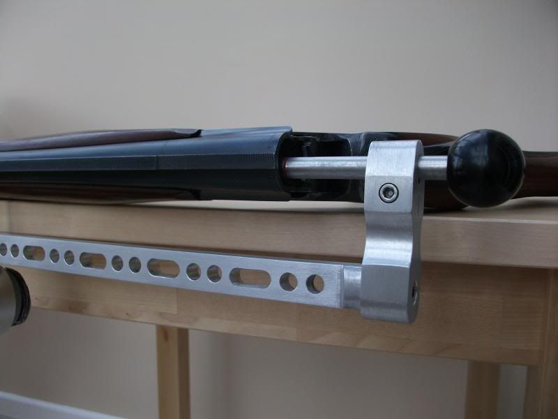
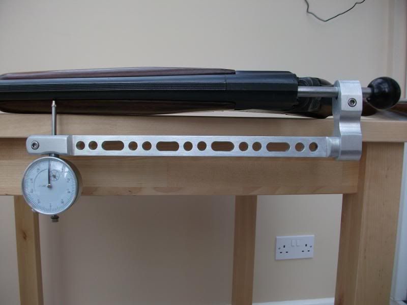
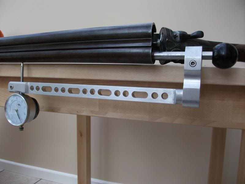
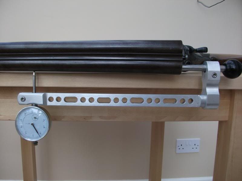
From the picture you will see that there are two bearing points on the gauge limb that enters the barrel. One is at the measuring point directly in line with the dial gauge and the other is placed a short distance away from the gauge point acting as a stabilizer/bearing. Also on the limb is a datum line that is cut in to the metal and filled with a coloured paint which is exactly 9 inches from the dial gauge measuring point.
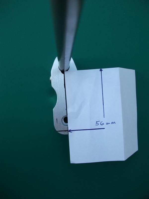
The lower limb or outside limb holds the dial gauge in a clamp joint allowing for zero adjustment though its position is set at a fixed distance from the mounting block. As there is a single screw used in its fixing to the mounting block the limb is free to rotate bringing the dial gauge plunger in to line with the mounting block’s central axis.
Now let’s start with the mounting block and the limb that enters the bore it is held in the block by a clamp joint which will allow full lateral and rotational movement, enabling the bearing measuring zero point to be brought into line with the dial gauge plunger and clamped firmly in that position, also this limb extends through the block to make a convenient mounting for the ball handle.
Now if you suspend the gauge from a flat surface you will observe that it will not sit on the zero reference point but on the stabilizer/bearing point. To bring the gauge to rest on the zero reference point we must add some form of counter weight, so as we proceed in making the gauge how we do this will become clearer.


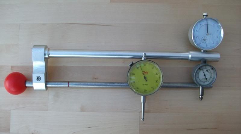
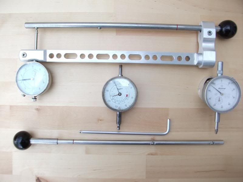
Various Dial Gauges used over the years

This is the list of bits and pieces you will need though keep it in mind that the sizes given are not set in tablets of stone so a little above or below the sizes I have recommended will be just fine. Now the way the world works here in Britland purchasing small amounts of metal on e-bay you use the nearest size you can because
Metric and Imperial sizes go hand in hand so I am not going to insult your intelligence by giving conversions from Metric to Imperial and visa versa.
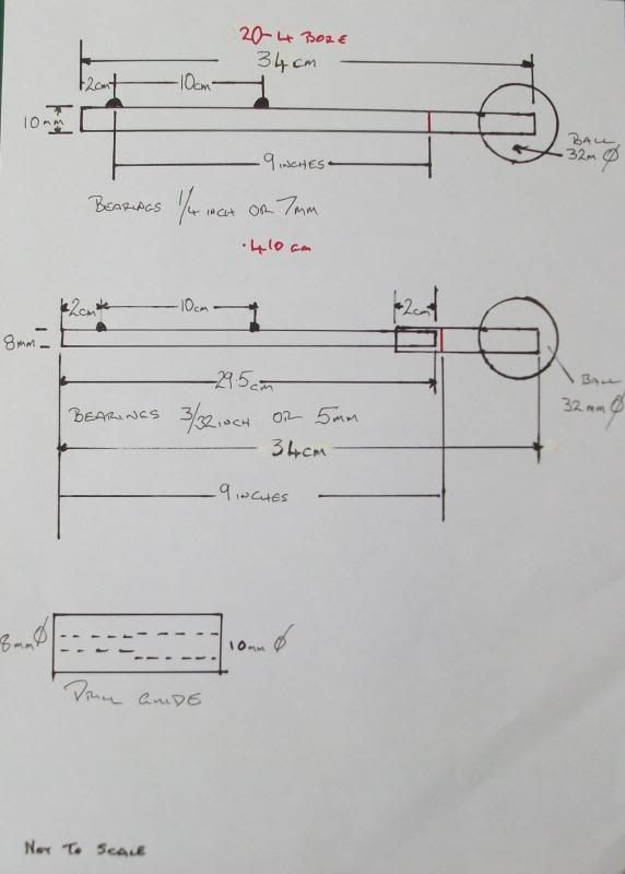
100mm 1¼ x 1¼ inch Aluminium bar. (This was cut from a larger section)
305mm 20mm square Aluminium bar.
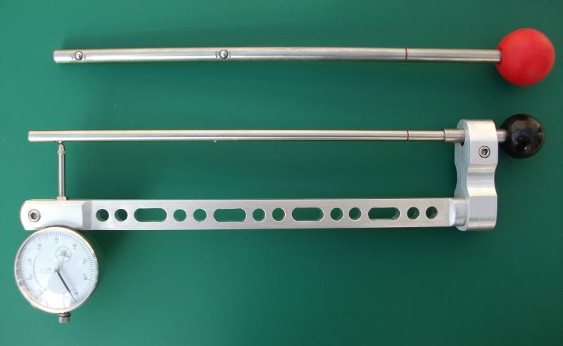
500 mm 10mm Stainless steel rod. For large bores
500mm 8mm Stainless steel rod. For small bores
2 5mm x 20mm hex cap screws. Use US equivalent thread sizes.
1 6mm x 25mm hex cap screws. ,,
2 7mm or ¼ in ball bearings for large bores. These bearings are a standard 2 5mm or 3/32in bearings for small bores. type found in pedal bicycles
2 Plastic knobs.
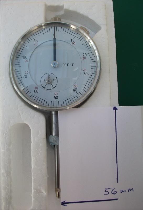
Dial Gauge Range 0 – 1 inch Reading 0.001 inch 2inch diameter. Or:-
Dial Gauge Range 0 – 10mm Reading 0.01 mm 60 mm diameter.

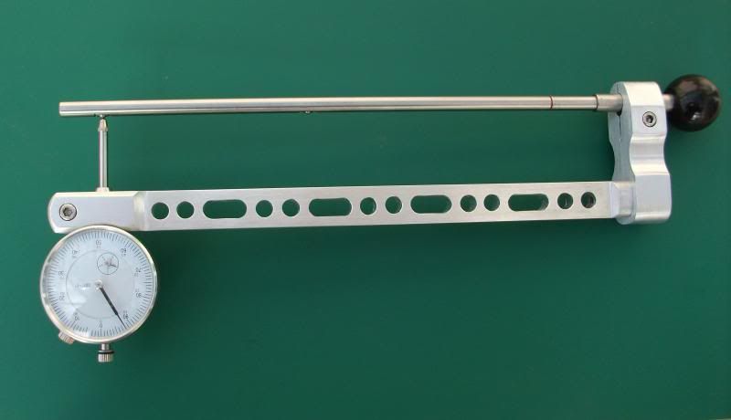
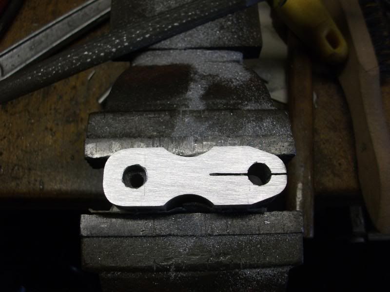
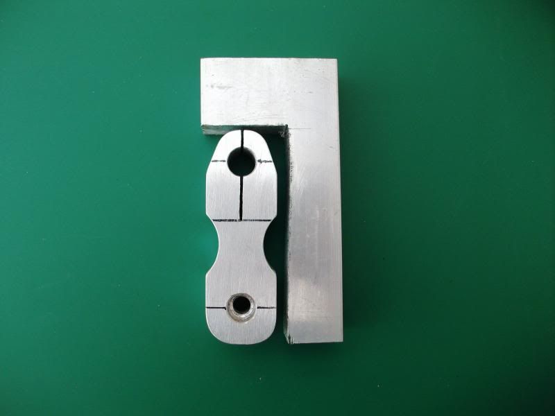
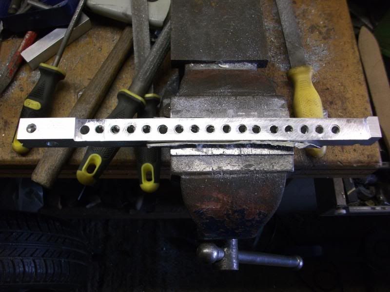
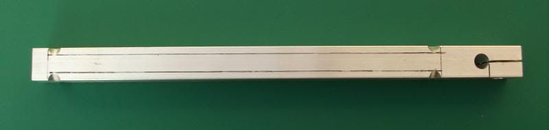
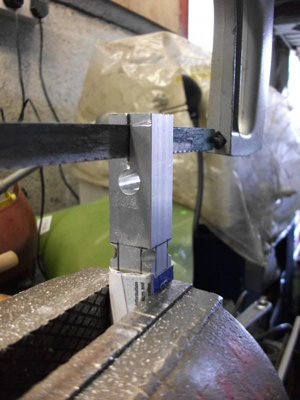
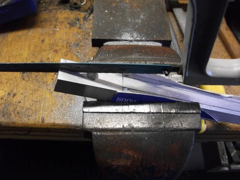
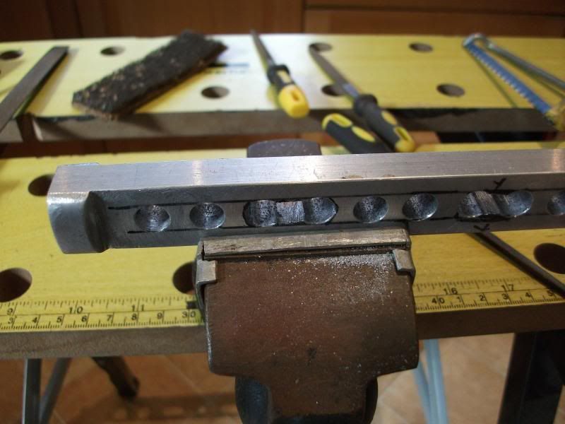
My first choice of material was Aluminium because it easy to cut and shape with hand tools as well as being light. You will notice from the first photograph the limb holding the Dial Gauge is round and the one in this article is made from square section the reason for this change is I did the shaping for the gauge using my lathe. But for this exercise hand tools and a drill press are the only tools to be used, also it is far more difficult in practice to hold centre and drill a round bar the so the use of the square made it far simpler square was used in all of my earlier designs. If you follow the drawings and remove the metal as shown the total weight of the gauge with the larger bore rod is 20 oz approximately 0.57 kg. I used stainless steel because it was available at the time at very little extra cost over mild steel and of course it does not rust though mild steel will work equally as well.
Because there are a number of photographs and drawings it is my intention to continue this posting in instalments because of its length also posting multi photographs is rather an arduous exercise because the image hosting site does not always do what you want. And on a personal note I did not appreciate how long a simple task takes to explain in writing. And lastly it can be a put off to people if there is to much talk so I feel it will be far less daunting to make the gauge if it is done in smaller parts.
very nice!
That's sweet. The design sure looks good to me. You should look into a patient or copyright. Beautiful workmanship also.
Interesting.
He's probably used it on several patients already!!
Looks like the Manson gauge from Brownells to me. $100 out the door.
Originally Posted By: Bilious Bob
Looks like the Manson gauge from Brownells to me. $100 out the door.


It's not the same when you can make it.

A different rendition, a table only model

Hi all

Well I see my gauge design did spark off some conversation.
Bilious you think it is a “Manson Gauge” now I wonder how that can be because of the following.

1 My gauge is designed to work in the horizontal suspended position only.
2 The gauge weighs approximately 20 ounces.
3 Only one adjustment needed after assembly. You have to be constantly adjusting a Manson gauge from barrel to barrel.
4 It is 13½ inches long
5 It is 4 ½ inches wide.
6 It will fit in our pocket.
7 It will only measure accurately 9 inches from the breach face
8 It is not always necessary to break the gun down and remove the barrels for measuring.

Now as the Manson gauge comes in a convenient “Large” wooden box which would cost more than my gauge takes to make. And of course it works in the vertical position only. Also the gauge arm for the smaller bores is a fixture to the gauge. It also weighs a considerable amount more and not all that convenient for taking and using at gun sales or auctions. And let’s be honest it does not slip conveniently in to your coat pocket now does it. Also you have to break the gun down to measure the barrels with a Manson. You may like to try that at some time with a $11307 value gun with the owner watching you because they always think you are going to drop them!!!!!!!!!!
And Bilious to quote your good self “It only costs $30 out the door” To make!
Finally I would like to say that accurate measuring tools have been made since that nice French man William Gascogne invented the Micrometer so in many ways test gauges look and work on very similar lines, my gauge is just a different take on an extremely old theme.

I will wait for more comments and see how much interest there is in going forward with how to make it before posting the how you do it.

Damascus
Damascus;
My take on this is "IGNORE" BB & let the Show Go on. I for one am interested in it, especially the use of the two balls. As a retired machinist I could build it from what you have already supplied, but not sure I understand the purpose of the 2nd ball.
Damascus,
please do go on with the excellent instructions

I intend to make one of these for my own use in my small workshop (EMCO Compact 5 lathe and small Clarke Mill) - should be sufficient for the task

Unfortunately I am not a trained engineer but find that I can make things by following instructions.

Thanks for sharing

Best regards
Günter
NRA Life 1974


This appears a near copy of the Hosford unit.

I also am curious about the second ball.
IMHO any secondary contact with the barrel will modify the reading as the contact will bear some weight (provide support).
Also why I prefer the horizontal version.
Very interesting topic. I recently bought the $100 Manson gauge from Brownells and found that it can be difficult to get an accurate reading. Worked best for me vertically when tied to a string hanging from a rafter. Directions say not to use horizontally and that's true as there is 0.020-0.030" flex just from the weight of the tool. I'm not sure how I'd use at a gun show without bringing a ladder to hang it from the ceiling, so much for the portable benefit.

I'm interested to learn more about how to get accurate & reliable wall thickness readings. Thanks.
If I may the second ball is part of the genius of his design. Rocking the instrument is one of the reasons for inaccurate readings with the Brownells' gauge. The two points give the operator reference. The truss construction of his design of the lower beam, the second part of the design genius, restricts the inaccuracies from bending experienced in the Brownells' gauge. All this in a portable instrument. I hope it works as good as it looks cause I think this instrument is a winner and I hope he can make some bucks with it.
Thanks for sharing the project Damascus. I also appreciate that it's still important to check even though I'd assume the first thing you'd look for is current proof marks.
I don't know what the length of the bar is or how far apart the balls are. Any distance greater than 10", in my opinion, is not a good idea, in case the bore is not straight. The one ball is better because you are only referencing one point, not two.

None of these gages are good for shows, as Damascus stated, most sellers would not like their guns taken apart with the possibility of being dropped or banged against something.

I've made a few different ones and like the Galazan's type best. I can do 16, 12 and 10 ga. breech to muzzle by flipping the barrel and setting the distance wherever I want and read from top to bottom rib.
The stock of the gauge is the starting point because it has one of the only two critical dimensions in the whole making of this gauge. The critical measurement is the distance between the gauges arms and is set by the dial gauge so you will need to have your dial indicator to start. Now looking at your gauge there is the measuring plunger and directly above this is a round mounting boss/collar that will be clamped in the external gauge arm you will need to know what diameter it is because the ranges of dial indicators are standard but this boss/collar size is not from one manufacturer to another. With the boss/collar size noted we now establish the maximum distance between the gauge arms that the dial gauge plunger will reach. And of course be zeroed, in other words it is the point the plunger must always be able to reach and sit on the zero bearing point with the smaller barrel rod fitted. These measurements can be established completely by measurement but that is not the way we will do it, every measurement will be taken from the parts you hold in your hand, less chance to have a disaster that way.


The easiest way to find the maximum distance of dial gauge travel you will need a piece of blue tack well that is what they call it here it is a blue tacky putty that can be used for hanging pictures etc on a wall but chewing gum will work admirably. Put the blue tack on the plunger shaft and gently push the plunger until the first zero point is reached on the dial that is both small and large hands are at “0” respectively. Now place a piece of paper between the bottom of the gauge housing and mark the end of the plunger on the paper my gauge distance was 56mm.


Now at this point I should say that I know we are suppose to speak the same language but I also know that descriptions somehow do not transfer across the pond to well so don’t guess if you do not understand just contact me by e-mail or via the site.
When you measure the distance that is the maximum distance the plunger is able reach under its own spring power. Just to make it clear that is the distance from the top of the limb that the dial gauge is mounted in to the bar that enters the barrel. Now I am intentionally ignoring the ball bearing that will eventually be fitted later which stands proud of the surface because I would rather have the distance a little too short than so long that the gauge plunger will not reach the bearing for zeroing.


Now we have the spacing measurement we can cut the gauge stock out of the aluminium block which is 25mm X 80mm X 20mm thick but extend each size by a couple of mm to allow for cleaning up etc next draw a centre line from top to bottom. The first hole to be drilled is the larger 10mm in the photograph positioned on the centre line 12 mm from the top surface, now this is the largest hole and the one more likely to drift while drilling also more likely to turn out over size which we do not want so we drill it with the next drill size below the finished hole size we want which was 9.5mm.


So now we are going to make a type of one time one use made on the job reamer once a tool room favourite rather than an expensive commercial offering out of the bar we will be using for the gauge limb its self, but you must remember it is not intended for removing large amounts of material. To make the reamer you take a 100 mm length from the steel that you intend to make the barrel limb out of and make a long sloping cut from one side to the other and then file the cut surface smooth in fact the smoother the better also it must have no burs on the sides. The reamer I made is in the photograph and to use it clamp the round section in a vice and lubricate it well and also the hole for aluminium I do prefer to use WD40 on aluminium you can sigh now!!!!!
Place the hole to be reamed to size on top of the reamer keeping it straight and as vertical as you can and turn slowly and try not to wobble while you are turning and applying a steady firm pressure, soon you will see after a couple of turns that it is removing fine shavings of aluminium, keep turning until the fully round section of the reamer passes through the hole the fitting should be a close fit indeed.
Next we determine where the opposite limb position is to be placed which is also positioned on the centre line. The opposite limb is made from 20mm square aluminium bar which the dial indicator is held in.


Now just to help and stop you getting lost place your reamer back in the hole you have made and then lay your piece of paper along the centre line touching the reamer and mark the aluminium (use pencil it comes off easier) where the end of your test dial plunger came to. You have now located the correct position for the other limb of the gauge that holds the dial indicator. Now the material for this limb is 20mm square its centre is 10 mm from each side so to position the mounting hole all you do is measure 10 mm from the line you have just transferred from the paper along the centre line towards your first hole and mark with a centre punch (a nail will work just as well). This hole is drilled clearance size for the 6mm screw. It was not until I started photographing parts for this gauge that I realised how bad the lens is in my digital camera is, I think I had better start saving for another!!


I did not make it truly clear about the 10mm hole its centre is 12mm from the top surface.
Just thought I would post some photographs on the way things progressed here.


Now we come to the gauges outer arm holding the dial indicator, in fact this is not difficult to make but in all honesty it does entail some lengthy work with a file and hacksaw. But there is always a but isn’t there, from a pure functionality stand point you have no need to do any further work other than drilling and threading the mounting hole at one end and making the clamp fitting with the dial indicator mounting hole at the other.
I think a little explanation is required here, this gauge is the end result of a considerable amount of trial and error over many years so what you see is the shortest strongest most accurate and above all the lightest usable version of the gauge to date, well who really wants to walk around all day with the weight of a battle ship in their pocket. To reduce the overall weight of the gauge further without compromising its rigidity I came up with the simple form of weight removal that you can see, the two holes and two holes sloted design but there are many others that could be used. It looks aesthetically pleasing (well to me it does) easily accomplished but as I have already said some work with a file and hacksaw is required though most of the work is just drilling holes and it can just stay at that just drilling the holes. Now I will post pictures on how I went about making this arm it might just help in your construction.


OOOps

The internal barrel limbs are a part of the gauge that can be a little trying to make but if you read this a few times before you start it should be of help. We will start first with a length of 10mm bar which is for twenty to 4 bore then tackle the .410 version after completing its larger brother should be a little easier to complete. First we have to find the centre of the bar and mark the bearing position, there is an old workshop trick to this that works every time though if you have a well tried method of your own use that. To start clamp the rod horizontally in a vice leaving about some 6 inches sticking out and then run over the top surface with a colourd felt tip pen (well who has “layout” blue these days) try to get a good thick coverage stand at the end of the bar not held in the vice, take hold of a flat file between finger and thumb of each hand with a space between you hands of about 1½ inches/40mm place the file on top of the rod in the vice with the thumb and index finger of one hand touching the side of the bar. Now press down on the file and pull the file quickly along the rod towards you and out of the open end. It will leave a shiny straight line on top of the rod for you to measure along. Next hold the bar in a vice with your marked line uppermost and mark the position for each bearing. It is good idea to mark the positions with a firm deep punch mark because you will need to file a small flat on the bar over the marks so when you start to drill the bearing hole the drill will have less tendency to wander, it is the same process for each rod in turn.
We need to drill the holes just a little over half the height of the ball bearings but that is far easier said than done because of the sizes involved. Now because the bearings do not have to rotate they are just set positions along the bar if you over drill the depth it will be fine put some metal packing under each bearing to bring them to the same height. Now to keep things stable until you grip them in the bar a little epoxy adhesive under each bearing with its packing will help greatly. Now my tried and tested method of fixing a ball bearing in a shaft is as follows, using a junior hacksaw make a shallow saw cut about a millimetre deep and about a millimetre from each side of the bearing hole then place a punch in the saw cut angled it towards the bearing and give it a sharp tap with a hammer to swage a piece of metal towards the bearing which will then be griped in its hole.
The smaller gauge limb is inserted in to a piece of 10 mm bar so that it can be clamped in the gauge without a lathe to centre the bar and drill it we have to use an older method once used by clockmakers. Take a piece of steel bar about two inches long and drill half way down its two inch length with a 10mm drill then drill the other half with a 8mm drill and what you will have made is a drilling guide, drilling the 10mm hole first the bottom of the hole shape helps to centre the smaller drill. Sometimes it is a good idea to give the outside of the drilling guide a few smart blows with a hammer all the way around to make it a tighter fit on the 10mm section helping to centre it further. You just fit the guide over the 10mm section and drill through the 8mm hole in the other end not forgetting to remove the drill from the hole from time to time to remove the swarf.


Damascus,

This is exemplary. I am not a machinist but as someone mentioned I can follow instructions and will be making one of these very soon. I expect the only difference in tools is I will use a band saw for some of the cutting.

I do have a question for others. I was trying to copy paste the thread into Word but it didn't work so well. I would like to copy/paste to an app that I can save for later use and make a hard copy to paste above my work bench. Suggestions on how to go about this would be appreciated.
neat
Tamid, I am using Windows 8 (not by my choice) and I can copy and paste that article in Word, then give it a title and put it where you want.
How the gauge design works


To make things clear about the second ball it is there only to provide a stable platform in a straight line to the reference point ball inside the bore for the gauge to operate correctly, it is also there to prevent rocking because there is no need to hold the gauge once you have inserted it in the barrel this in turn eliminates hand tremble and hold errors because the gauge relies ONLY on gravity to affect a stable reading and its inherent weight also pulls the gauge to the lowest point on the barrels internal curve. The stabilizer/ bearing plays no direct role in measurement at all because all measurements are made strictly between the measuring point ball which is held firmly against the barrels internal surface by gravity acting on the total weight of the gauge, and the measuring ball is the only point directly in line with the dial gauge plunger. Now the distance between the balls is four inches and was found to be the ideal distance by trial and error over many years, less than four inches enabled the gauge to rock easily. Extending the distance between the balls meant that you also needed to extend the gauge’s length and by doing so you started to increase flexing errors If you kept the gauge length the same and still extended the distance between the balls on long chamber guns the stabilizer/bearing could end up positioned in the guns chamber and making a true reading impossible. If you put the gauge into a barrel at this point it will come to rest on the stabilizer/bearing and limb rather than the measuring point and stabilizer/guide bearing purely because of the gauges combined weight past the stabilizing/ bearing balance point thus causing the gauge to act in this manner. This is caused today by the lack of weight and mass of the dial gauge, when I first started this project dial gauge bodies where made from a brass casting weighing in at around 7 ounces which was more than enough to pull the reference point ball into contact with the surface. But today modern dial gauges are made from aluminium and weighing about half the weight of their predecessors, if you feel that you are putting to much weight on the dial gauge you can fit screw on extra weights either side of the external limb by the dial gauge clamp joint especially if you want to use a digital dial gauge. I have also included my very first dial gauge in the completed gauge photograph because it was in at the start of this project though it is now not functioning correctly because of the large amount of internal ware it sustained over some forty years of nearly use and it is now one of my keep for life objects because it was a workshop slave when I was.


There is a sound reason why I have not included the additional weight in the gauges physical construction to bring the correct balance which is I use different dial gauges in conjunction with the gauge also the gauge’s basic design is so right. One gives Imperial measurement and the other is Metric neither dial gauge weighs the same (the Baty fitted in the gauge weighs 3.5oz and the Mitutoyo weighs 5.5oz) weight or has the same physical dimensions they are manufactured by two different makers this also accounts for the extra shaping of the external limb under the base of dial gauge, so to keep things simple it is far easier to add weight to the dial gauge making replacement far simpler this also makes good sense because it is the only part of the wall thickness gauge liable to break down in some way. Finally talking about dial gauges you could spend a lot of cash and purchase a digital dial gauge but I personally have reservations about them, they seem to weigh next to nothing and are blown of the bench when you sneeze though it also may be just bad luck on my part but my experience of one is that when I need the “D###” thing the battery is flat or when I eventually get around to using it the battery starts to fail so you pays your money and takes your chance it is your decision. To calculate the weight needed to hold the gauges measuring point ball firmly in contact with the barrel’s internal surface the manufactures of dial gauges kindly put a convenient mounting point for the required weight that is always in direct line with the plunger on the back of the gauge. Tie a piece of cotton to the mounting point with a bolt fixed to the other end then add nuts until the gauge comes rest on to the zero point and in doing so the gauge will now be sitting on both zero and stabilizer/bearing points, weigh the bolt and all the nuts then add a minimum of fifty percent more weight and adjust a separate piece of metal to this combined weight and fix to the back of the dial gauge, I like to use silicon rubber it holds well and you can remove the weight from the gauge quite easily. By adding weight to the external limb this also preloads the limb inside the barrel and in doing so reduces further the amount it can flex inside the barrel this is lost important to the .410 version because of its slender design. The lesson all those years ago in the workshop with sitting on the “I” beam was not wasted at all!!!!!!!!!!!!!!!!!
I thought at this point I should post some photographs of the gauge in use. Please note the guns are all complete and not striped down and the Gauge enters without a problem on the “side by side, side by side hammer, and the over and under,” though they are all 12 bores in the pictures though I am sure that you can see the way the gauge hangs differing bore sizes will make no difference to the gauges functionality.


My last posting will be how to zero the gauge but I do feel sure if you have made it this far that you will have guessed by now the how and the why.
Posted By: damascus How to zero the gauge - 03/21/13 12:40 PM
zeroing the Gauge

Now comes the most important procedure zeroing the gauge, to start align the dial gauge point and its opposite point on the limb that enters the bore there is no reason at this stage to try to zero the gauge. You next suspend the gauge from two fixed points (I use two nails driven into the front face of a shelf) one close to the measuring zero point and one next to the stabilizer/bearing point. This causes the limb that enters the barrel to flex because of the weight of the gauge, it is only now that you can truly zero the gauge by moving the dial indicator closer or further away from the zero point on the limb that enters the barrel. This is the result of that lesson given to me in the workshop by that rather rotund engineer all those years before no matter how strong the object if you apply a weight it will flex. Zeroing the gauge is a bit of a trial especially when using the thinner barrel limb used for the smaller bores but being able to zero the gauge easily will come with a little practice.
To take a reading at all you just push the gauge into the barrel as far as the 9 inch mark and take your hand away gravity will do the rest!

For those who are making this gauge I do hope all goes well. I have been thinking about what to call this effort of mine and I do think a "MARRIOTT GAUGE" should fit the bill.

Good luck Damascus
Posted By: eightbore Re: How to zero the gauge - 03/21/13 02:20 PM
The Marriott gauge is a wonderful effort. However, I am amazed that so many people still think the Manson gauge is hard to use and inaccurate. Some continue to think it cannot be used in the horizontal position. The horizontal position is the simplest and most accurate method by far. Some still think that rod flex is a problem with the Manson. It is not. I have explained in plain language, in past threads, how to use the Manson gauge, yet many seem to ignore the simple instructions, mine, not Brownell's. I guess I could make a video, but it would affect Jon Hosford's business, and I don't want to do that.
Originally Posted By: JDW
Tamid, I am using Windows 8 (not by my choice) and I can copy and paste that article in Word, then give it a title and put it where you want.


JDW

Thank you for the offer. I opened it at work, flipped the pages to landscape and was able to copy /paste without any cropping. For some reason it wasn't working quite so well with my Mac.

Cheers
Posted By: David Williamson Re: How to zero the gauge - 03/21/13 02:59 PM
eightbore, the problem I see with both the Hosford and Manson is that in doing the bore readings from the breech, you need someone to hold the barrels down as you try and get readings. Not always possible to get those extra hands and turn for readings.

The flex part is not a problem doing it your way, as the rod is almost floating by holding it with a string or ring.

For home, I will still take the Galazan type gage I made. I can do 10, 12, and 16 ga. If the choke is to tight and I cannot insert it on said rod, I can move it over to the next smaller rod and re-calibrate the needle.
Easy to take readings from top rib to bottom rib and read all from this position and still write down the readings which I do on all guns I do.

The above gage by Damascus from what I see is only a little over 13" long. Good for 26" barrels but would leave a void on longer ones.
Posted By: damascus Re: How to zero the gauge - 03/22/13 10:47 AM
Hi all I think after getting to the end of this project I should restate a few things.

The gauges primary function is to check the barrel wall thickness at the “BRITISH STANDARD PROOF DISTANCE OF 9 INCHES FROM THE STANDING BREACH FACE” !!!!!!!!!!!!!
The gauge is not at all intended for checking the total internal barrel length for pitting or flaws, it is an aid in helping you decide how to proceed, firstly you measure the wall thickness at 9 inches and it is lets say it is X thousands of an inch your decision now is how much metal would be left in the barrel walls if the marks or pitting where to be removed and would it be safe to use or sell?
Or how thick are the walls of this gun at 9 inches from the breach face given that there are no marks or pitting in the bore? Depending on the wall thickness is there a high probability it has been back bored to remove pitting or marking?

DO I PURCHASE THIS GUN YES/NO ?

Also the primary design criteria for the gauge was that it could be used without the need to break down a gun to check the barrels independently, and most importantly can I undertake to check the wall thickness of the barrels at 9inches without the help of another person holding the gun.YES! It does that perfectly.
And finally can I put it in a coat pocket? It will also do that for you to!! It is primary purpose in life was to be used at gun sales and auctions to make that decision do I take an interest in this gun or walk past it, there are a plethora of other tools for inspecting gun barrels at leasure in the comfort of your own home or workshop.

Damascus
Posted By: Drew Hause Re: How to zero the gauge - 05/19/13 10:45 PM
A member here, and SE AZ winter visitor, very kindly made me a gauge. I am NOT mechanically inclined but Gloria a Dios the dang thing is easy to use, and works!!

With the .038 curved strip to zero the micrometer


Top to bottom:
Upper arm with brass stop
Micrometer leg under spring pressure
Lower arm with screw to tighten a brass shim (inside the arm) to hold the micrometer in place


24" plastic tool box with 2 bungie cords holding the barrel. It was quite steady with the usual gun cleaning stuff inside, and the cords allowed the barrel to be rotated and ends swapped


Muzzle extending well past the box, with 20" of yardstick


Measuring the wall thickness per the Hosford YouTube
http://www.youtube.com/watch?v=1jQZn4kohH4


I started with Fox barrels that Briley honed from .724 to .727, or .0015 from the barrel wall, completely removing what I had thought were fairly deep pits.

Measurements were very consistent right/left and the length of the bore:
Just past the forcing cone which I had Briley lengthen - .110
9" from the breech - .045 then to .034 the remainder of the bore until the start of the choke constriction.

I'm very pleased with the gauge, and owe my friend a nice meal and drinks in Sonoita next winter!!
Posted By: damascus Re: How to zero the gauge - 05/20/13 09:43 AM
Hi drew.
I do enjoy seeing things people produce for them selves and cutting out the expensive manufacturer and the middle man. I hope you do not mind me pointing out one small detail that I think you should be aware of which is the upper arm Brass stop. Brass and Steel do not make good bed fellows and especially where the slightly acidic environment of gun bores are concerned especially if the bore is not Chrome plated. To put it in a nut shell standard steel barrels and microscopic brass particles that could possibly be left in the bore after using your gauge can sometimes lead to some electrolytic action taking place encouraging rust spotting, which can be more easily produced in mix metal barrels i.e. Damascus and twist. This is not a problem with bore cleaning brushes because they are made of the less reactive bronze. So I think that replacing the stop with one made out of Steel or Bronze would be a wise move.

Damascus
Posted By: Drew Hause Re: How to zero the gauge - 05/20/13 02:08 PM
Thank you Damascus. Is this not a problem with brass shell heads? And what could this fellow have been thinking!?! shocked

Posted By: Stallones Re: How to zero the gauge - 05/20/13 03:24 PM
Here is another Make it at Home. Kinda lacking in the professional
area,but it works.
[img:left][/img]
Posted By: damascus Re: How to zero the gauge - 05/20/13 06:53 PM
Hi Stallones

It is always a good thing to keep reminding your self, “professionals built and sailed the Titanic Noah was a complete amateur”.
Posted By: damascus Re: How to zero the gauge - 05/20/13 07:35 PM
Drew I can not speak for what others are thinking, though if the Brazing rod used was a Copper/Silver or Copper/Nickel Alloy I could see no problem in using it for joining steel/Iron. But to repair a gun barrel like that it is sort of buying your self a ticket to oblivion or a hospital emergency room from a roulette table. And if you want to use a brass stop that is also fine though I would decline its use in a gun of mine.
Posted By: eightbore Re: How to zero the gauge - 05/21/13 01:05 AM
Damascus, I do like to have a helper to hold the gun or barrels down. Please explain to me how you measure your guns with your gauge without holding the gun down. As we say in the USA, "Give me a break." The Manson gauge, used the way I have explained many times on this forum, is a great tool and cheap. And also, in the USA, we don't respect British proof and want to know the measurements for more than nine inches of our barrels. I am not disrespecting your effort or your gauge, I just don't appreciate your disrespecting my gauge without knowing anything about it or its proper use. The "hanging" method is obsolete, but you and some other posters apparently don't know that.
Posted By: damascus Re: How to zero the gauge - 05/21/13 10:25 AM
Eightbore

You seem to be behaving like a person who has great vested interest in proving only your gauge is the correct one to the point of disrespecting other forum users (your choice of words) by suggesting that they do not know how your gauge functions. I am sure they do! Some how you seem to have this idea that I, and I am only going to use myself in this case and not speak for others that I am concerned in the slightest that the US does not respect Brit proof it is your house and you live in it as you please.
Over the Brit proof distance of nine inches you seem to want to talk for the shooting population of the US which I feel is extremely brave or foolhardy putting words into other people’s mouths.
Holding the gun down!!! There are six photographs on page three of the posting the answer to that is quite obvious isn’t it?
Your statement “the hanging method is obsolete” I can only wonder at such an incredulous statement on your part.

Hi all

Well I see my gauge design did spark off some conversation.
Bilious you think it is a “Manson Gauge” now I wonder how that can be because of the following.

1 My gauge is designed to work in the horizontal suspended position only.
2 The gauge weighs approximately 20 ounces.
3 Only one adjustment needed after assembly. You have to be constantly adjusting a Manson gauge from barrel to barrel.
4 It is 13½ inches long
5 It is 4 ½ inches wide.
6 It will fit in our pocket.
7 It will only measure accurately 9 inches from the breach face
8 It is not always necessary to break the gun down and remove the barrels for measuring.

Now as the Manson gauge comes in a convenient “Large” wooden box which would cost more than my gauge takes to make. And of course it works in the vertical position only. Also the gauge arm for the smaller bores is a fixture to the gauge. It also weighs a considerable amount more and not all that convenient for taking and using at gun sales or auctions. And let’s be honest it does not slip conveniently in to your coat pocket now does it. Also you have to break the gun down to measure the barrels with a Manson. You may like to try that at some time with a $11307 value gun with the owner watching you because they always think you are going to drop them!!!!!!!!!!
And Bilious to quote your good self “It only costs $30 out the door” To make!
Finally I would like to say that accurate measuring tools have been made since that nice French man William Gascogne invented the Micrometer so in many ways test gauges look and work on very similar lines, my gauge is just a different take on an extremely old theme.

I

I have re-posted my observations and I can not see any inaccuracies but you are free to point them out.
The gauge I designed the how and why it worked has been up front from the very beginning and my personal opinion of you crying foul at this late stage is extremely churlish on your part, also I am extremely surprised at your comment “I don’t know any thing about your gauge or its proper use I feel you should have known better than to even suggest that.

My design has always been on the basis of here it is the way it works is explained you are free to make it if you wish. **** END OF ****
Posted By: eightbore Re: How to zero the gauge - 05/21/13 12:39 PM
The Manson gauge is used (in its most efficient manner) horizontally, just like yours. Yes, as you refuse to realize, the vertical use of the Manson gauge is obsolete. I have explained the quite simple horizontal method many times on this forum. The Manson gauge does not come in a wooden box that costs more than your gauge. I have never seen such a box for a Manson gauge. The Manson gauge, no box, is $100 and will measure way more than nine inches. British proof doesn't mean nearly as much to us as wall thickness throughout the entire length of the tube. Your pictures on page three are a representation of exactly how the Manson gauge is used in the horizontal position. Oddly, you have saved me from having to post pictures. Yours work just fine.
Posted By: damascus Re: How to zero the gauge - 05/21/13 03:40 PM
Eightbore.

Life and time is far to valuable to spend splitting hairs with you, also you seem to be of the opinion you are talking to someone who actually cares I gave the design away for any person to make and use. I think I will let Rhett Butler of “Gone with the wind” give you my final word on this subject “Frankly _ _ _ _ _ _ _.” And let people who have at least gone to the trouble to make one give their objective opinions.

Damascus
Posted By: eightbore Re: How to zero the gauge - 05/21/13 04:51 PM
For anyone who is interested, I will give a five minute demonstration, with no written instructions, of how to use a Manson gauge, at the Northeast Side by Side Shoot or the Fall Southern Side by Side shoot. Using the earlier poster's suggestion of the tool box and bungee cord, no helper is neccesary. The tool demonstrated by Damascus is a wonderful invention and I am interested to see it in action. To correct a couple of comments, the Manson gauge is used horizontally, the Manson gauge does not have to be adjusted for different barrels. However, the Manson gauge is not light, it weighs 48 ounces and will not fit in your pocket. The Manson gauge will measure any point of your barrel from breech or muzzle to 16 inches into the bore either way. If you want it to measure 9 inches, you can saw off the bars seven inches and reinstall them in the block. I never meant to critique the gauge being discussed in this thread, I only meant to correct the posters' comments that the Manson gauge cannot be used horizontally and that it comes in an expensive box. I didn't expect such a reaction.
Posted By: Run With The Fox Re: How to zero the gauge - 05/21/13 06:24 PM
Originally Posted By: damascus
Eightbore.

Life and time is far to valuable to spend splitting hairs with you, also you seem to be of the opinion you are talking to someone who actually cares I gave the design away for any person to make and use. I think I will let Rhett Butler of “Gone with the wind” give you my final word on this subject “Frankly _ _ _ _ _ _ _.” And let people who have at least gone to the trouble to make one give their objective opinions.

Damascus Well said indeed, Sir! I prefer the Jon Hosford gauges- are you familiar with them perchance. Life is waaay too short for hair splitting over such pettifogging details- if the shotgun in question shoots to POA, fits you, and you kill birds well enough with it, the rest is, to borrow a word from Lewis Carroll- "Brillig"! From my personal point of view, we have on the DoubleGunWorkShoppe run by our genial host Dave Weber- a miss-mash of members from specific side-by-side double gun collecting associations-

Some, but surely not all, of those "gentleman" will argue with you until Henry the 8th is re-incarnated and forgives Anne Boylen for sleeping around whilst they were married- argue about how much mustard Gottleib Anschutz's Frau put on his liverwurst and onion sandwiches in 1921 (He was a frame filing shop foreman at Parker Brothers in CT. then, by the by!!
Posted By: Drew Hause Re: How to zero the gauge - 05/24/13 10:43 PM
Found an old internet thread on the result of 'honing' a Fox Sterlingworth with a resultant bore of .739 and wall thickness of .018. Purchased from a dealer, and with the 3rd shot:


© The DoubleGun BBS @ doublegunshop.com