April
S M T W T F S
1 2 3 4 5 6
7 8 9 10 11 12 13
14 15 16 17 18 19 20
21 22 23 24 25 26 27
28 29 30
Who's Online Now
4 members (graybeardtmm3, canvasback, smlekid, 1 invisible), 530 guests, and 5 robots.
Key: Admin, Global Mod, Mod
Forum Statistics
Forums10
Topics38,465
Posts545,072
Members14,409
Most Online1,258
Mar 29th, 2024
Previous Thread
Next Thread
Print Thread
Page 2 of 5 1 2 3 4 5
Joined: Jan 2009
Posts: 386
Likes: 10
Sidelock
**
Offline
Sidelock
**

Joined: Jan 2009
Posts: 386
Likes: 10
This appears a near copy of the Hosford unit.

I also am curious about the second ball.
IMHO any secondary contact with the barrel will modify the reading as the contact will bear some weight (provide support).
Also why I prefer the horizontal version.


Dumb, but learning...Prof Em, BSc(ME), CAE (FYI)
Joined: Dec 2006
Posts: 21
Boxlock
Offline
Boxlock

Joined: Dec 2006
Posts: 21
Very interesting topic. I recently bought the $100 Manson gauge from Brownells and found that it can be difficult to get an accurate reading. Worked best for me vertically when tied to a string hanging from a rafter. Directions say not to use horizontally and that's true as there is 0.020-0.030" flex just from the weight of the tool. I'm not sure how I'd use at a gun show without bringing a ladder to hang it from the ceiling, so much for the portable benefit.

I'm interested to learn more about how to get accurate & reliable wall thickness readings. Thanks.

Joined: Mar 2005
Posts: 709
Sidelock
**
Offline
Sidelock
**

Joined: Mar 2005
Posts: 709
If I may the second ball is part of the genius of his design. Rocking the instrument is one of the reasons for inaccurate readings with the Brownells' gauge. The two points give the operator reference. The truss construction of his design of the lower beam, the second part of the design genius, restricts the inaccuracies from bending experienced in the Brownells' gauge. All this in a portable instrument. I hope it works as good as it looks cause I think this instrument is a winner and I hope he can make some bucks with it.

Joined: Feb 2009
Posts: 7,463
Likes: 212
Sidelock
**
Offline
Sidelock
**

Joined: Feb 2009
Posts: 7,463
Likes: 212
Thanks for sharing the project Damascus. I also appreciate that it's still important to check even though I'd assume the first thing you'd look for is current proof marks.

Joined: Feb 2006
Posts: 3,728
Likes: 50
Sidelock
**
Offline
Sidelock
**

Joined: Feb 2006
Posts: 3,728
Likes: 50
I don't know what the length of the bar is or how far apart the balls are. Any distance greater than 10", in my opinion, is not a good idea, in case the bore is not straight. The one ball is better because you are only referencing one point, not two.

None of these gages are good for shows, as Damascus stated, most sellers would not like their guns taken apart with the possibility of being dropped or banged against something.

I've made a few different ones and like the Galazan's type best. I can do 16, 12 and 10 ga. breech to muzzle by flipping the barrel and setting the distance wherever I want and read from top to bottom rib.

Last edited by JDW; 03/17/13 12:45 PM.

David


Joined: Jan 2013
Posts: 1,124
Likes: 195
Sidelock
***
OP Offline
Sidelock
***

Joined: Jan 2013
Posts: 1,124
Likes: 195
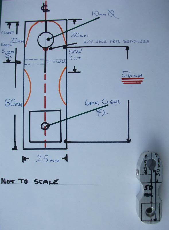
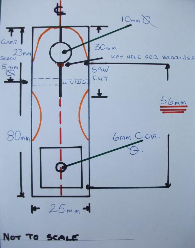
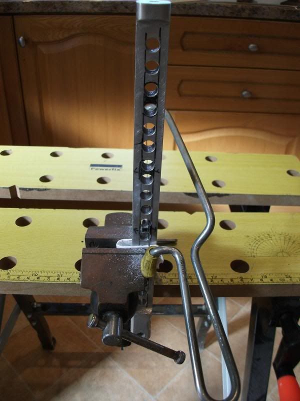
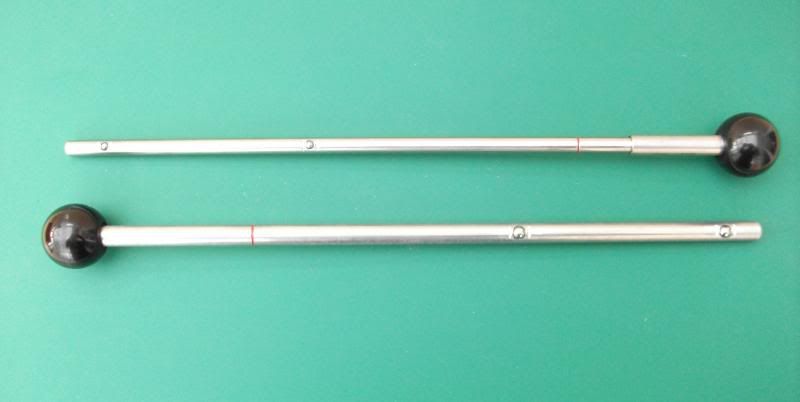
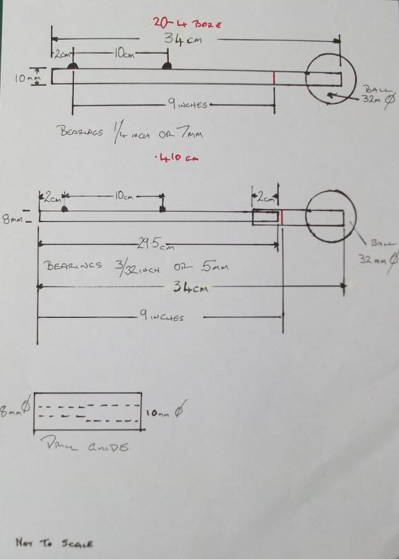
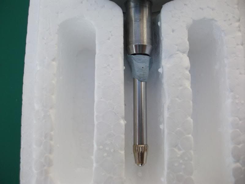
The stock of the gauge is the starting point because it has one of the only two critical dimensions in the whole making of this gauge. The critical measurement is the distance between the gauges arms and is set by the dial gauge so you will need to have your dial indicator to start. Now looking at your gauge there is the measuring plunger and directly above this is a round mounting boss/collar that will be clamped in the external gauge arm you will need to know what diameter it is because the ranges of dial indicators are standard but this boss/collar size is not from one manufacturer to another. With the boss/collar size noted we now establish the maximum distance between the gauge arms that the dial gauge plunger will reach. And of course be zeroed, in other words it is the point the plunger must always be able to reach and sit on the zero bearing point with the smaller barrel rod fitted. These measurements can be established completely by measurement but that is not the way we will do it, every measurement will be taken from the parts you hold in your hand, less chance to have a disaster that way.


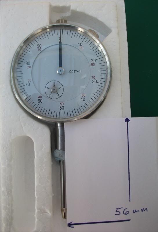
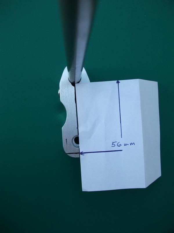
The easiest way to find the maximum distance of dial gauge travel you will need a piece of blue tack well that is what they call it here it is a blue tacky putty that can be used for hanging pictures etc on a wall but chewing gum will work admirably. Put the blue tack on the plunger shaft and gently push the plunger until the first zero point is reached on the dial that is both small and large hands are at “0” respectively. Now place a piece of paper between the bottom of the gauge housing and mark the end of the plunger on the paper my gauge distance was 56mm.


Now at this point I should say that I know we are suppose to speak the same language but I also know that descriptions somehow do not transfer across the pond to well so don’t guess if you do not understand just contact me by e-mail or via the site.
When you measure the distance that is the maximum distance the plunger is able reach under its own spring power. Just to make it clear that is the distance from the top of the limb that the dial gauge is mounted in to the bar that enters the barrel. Now I am intentionally ignoring the ball bearing that will eventually be fitted later which stands proud of the surface because I would rather have the distance a little too short than so long that the gauge plunger will not reach the bearing for zeroing.


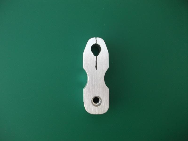
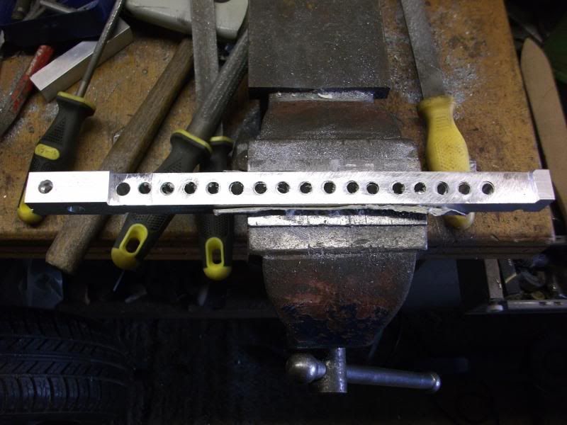
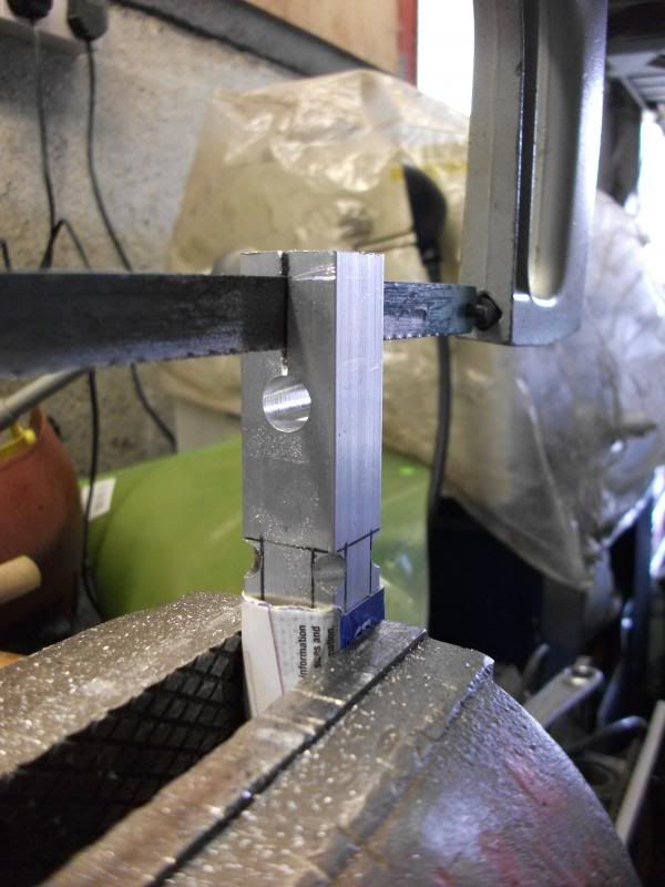
Now we have the spacing measurement we can cut the gauge stock out of the aluminium block which is 25mm X 80mm X 20mm thick but extend each size by a couple of mm to allow for cleaning up etc next draw a centre line from top to bottom. The first hole to be drilled is the larger 10mm in the photograph positioned on the centre line 12 mm from the top surface, now this is the largest hole and the one more likely to drift while drilling also more likely to turn out over size which we do not want so we drill it with the next drill size below the finished hole size we want which was 9.5mm.


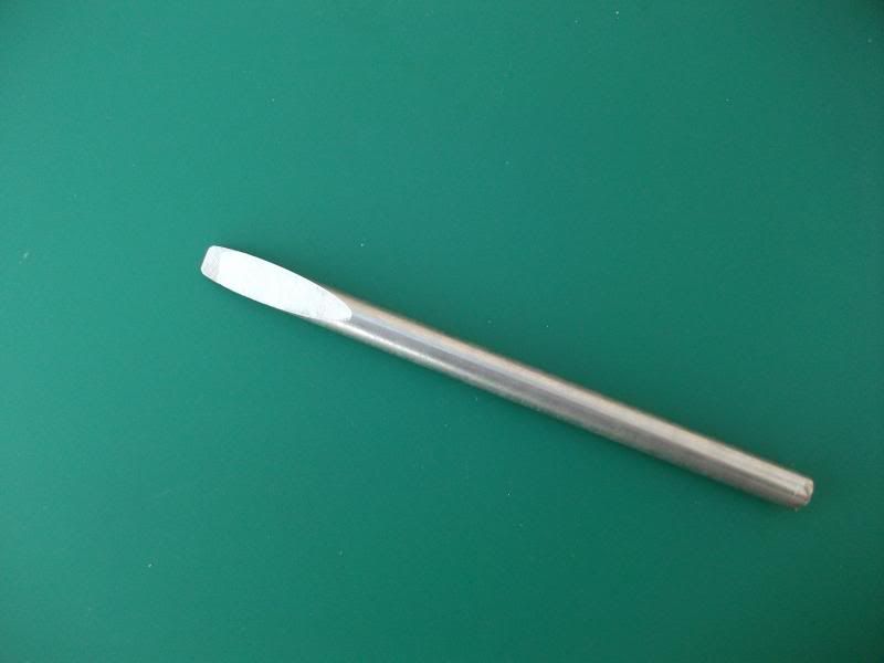
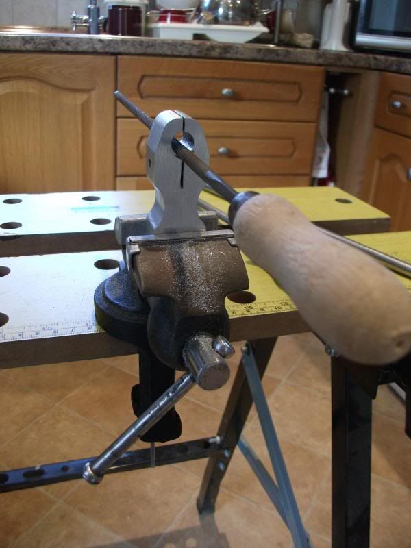
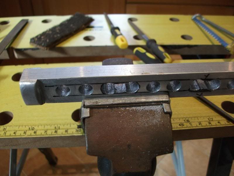
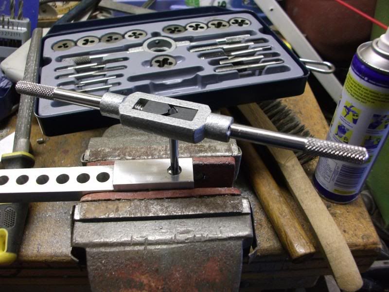
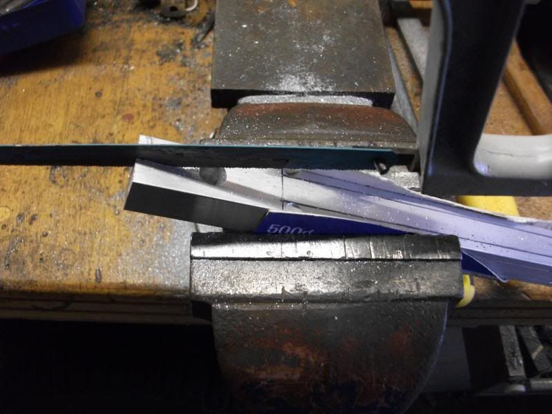
So now we are going to make a type of one time one use made on the job reamer once a tool room favourite rather than an expensive commercial offering out of the bar we will be using for the gauge limb its self, but you must remember it is not intended for removing large amounts of material. To make the reamer you take a 100 mm length from the steel that you intend to make the barrel limb out of and make a long sloping cut from one side to the other and then file the cut surface smooth in fact the smoother the better also it must have no burs on the sides. The reamer I made is in the photograph and to use it clamp the round section in a vice and lubricate it well and also the hole for aluminium I do prefer to use WD40 on aluminium you can sigh now!!!!!
Place the hole to be reamed to size on top of the reamer keeping it straight and as vertical as you can and turn slowly and try not to wobble while you are turning and applying a steady firm pressure, soon you will see after a couple of turns that it is removing fine shavings of aluminium, keep turning until the fully round section of the reamer passes through the hole the fitting should be a close fit indeed.
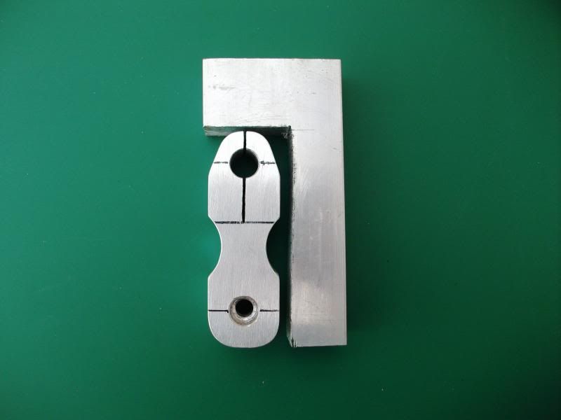
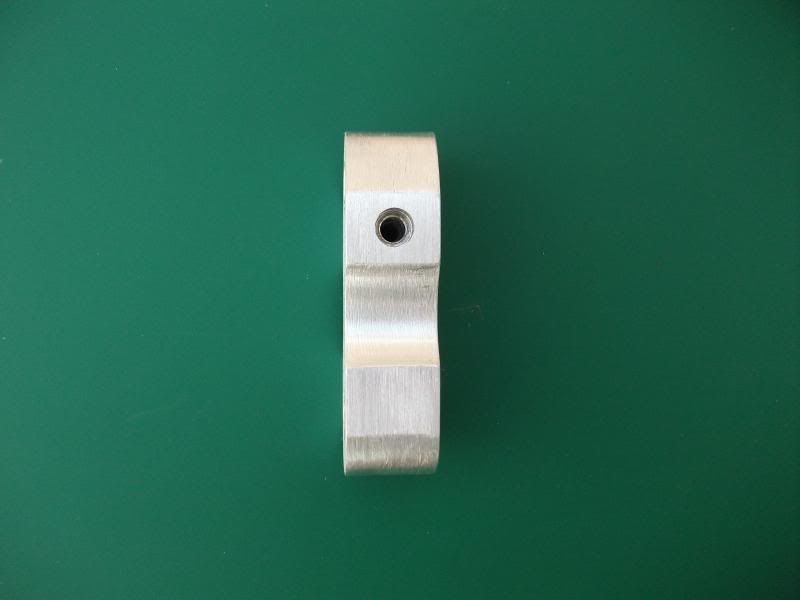
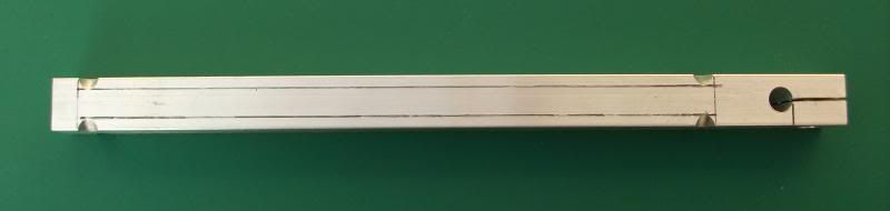
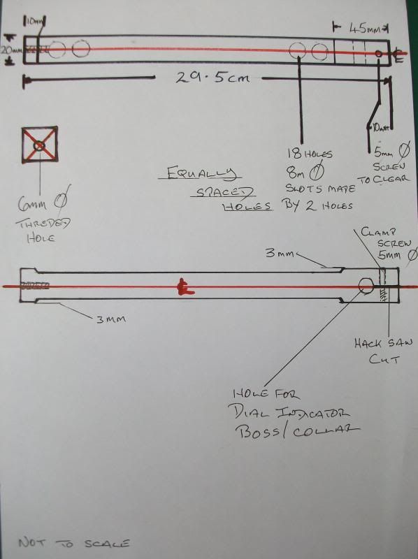
Next we determine where the opposite limb position is to be placed which is also positioned on the centre line. The opposite limb is made from 20mm square aluminium bar which the dial indicator is held in.


Now just to help and stop you getting lost place your reamer back in the hole you have made and then lay your piece of paper along the centre line touching the reamer and mark the aluminium (use pencil it comes off easier) where the end of your test dial plunger came to. You have now located the correct position for the other limb of the gauge that holds the dial indicator. Now the material for this limb is 20mm square its centre is 10 mm from each side so to position the mounting hole all you do is measure 10 mm from the line you have just transferred from the paper along the centre line towards your first hole and mark with a centre punch (a nail will work just as well). This hole is drilled clearance size for the 6mm screw. It was not until I started photographing parts for this gauge that I realised how bad the lens is in my digital camera is, I think I had better start saving for another!!


The only lessons in my life I truly did learn from where the ones I paid for!
Joined: Jan 2013
Posts: 1,124
Likes: 195
Sidelock
***
OP Offline
Sidelock
***

Joined: Jan 2013
Posts: 1,124
Likes: 195
I did not make it truly clear about the 10mm hole its centre is 12mm from the top surface.
Just thought I would post some photographs on the way things progressed here.


The only lessons in my life I truly did learn from where the ones I paid for!
Joined: Jan 2013
Posts: 1,124
Likes: 195
Sidelock
***
OP Offline
Sidelock
***

Joined: Jan 2013
Posts: 1,124
Likes: 195
Now we come to the gauges outer arm holding the dial indicator, in fact this is not difficult to make but in all honesty it does entail some lengthy work with a file and hacksaw. But there is always a but isn’t there, from a pure functionality stand point you have no need to do any further work other than drilling and threading the mounting hole at one end and making the clamp fitting with the dial indicator mounting hole at the other.
I think a little explanation is required here, this gauge is the end result of a considerable amount of trial and error over many years so what you see is the shortest strongest most accurate and above all the lightest usable version of the gauge to date, well who really wants to walk around all day with the weight of a battle ship in their pocket. To reduce the overall weight of the gauge further without compromising its rigidity I came up with the simple form of weight removal that you can see, the two holes and two holes sloted design but there are many others that could be used. It looks aesthetically pleasing (well to me it does) easily accomplished but as I have already said some work with a file and hacksaw is required though most of the work is just drilling holes and it can just stay at that just drilling the holes. Now I will post pictures on how I went about making this arm it might just help in your construction.


The only lessons in my life I truly did learn from where the ones I paid for!
Joined: Jan 2013
Posts: 1,124
Likes: 195
Sidelock
***
OP Offline
Sidelock
***

Joined: Jan 2013
Posts: 1,124
Likes: 195
OOOps


The only lessons in my life I truly did learn from where the ones I paid for!
Joined: Jan 2013
Posts: 1,124
Likes: 195
Sidelock
***
OP Offline
Sidelock
***

Joined: Jan 2013
Posts: 1,124
Likes: 195
The internal barrel limbs are a part of the gauge that can be a little trying to make but if you read this a few times before you start it should be of help. We will start first with a length of 10mm bar which is for twenty to 4 bore then tackle the .410 version after completing its larger brother should be a little easier to complete. First we have to find the centre of the bar and mark the bearing position, there is an old workshop trick to this that works every time though if you have a well tried method of your own use that. To start clamp the rod horizontally in a vice leaving about some 6 inches sticking out and then run over the top surface with a colourd felt tip pen (well who has “layout” blue these days) try to get a good thick coverage stand at the end of the bar not held in the vice, take hold of a flat file between finger and thumb of each hand with a space between you hands of about 1˝ inches/40mm place the file on top of the rod in the vice with the thumb and index finger of one hand touching the side of the bar. Now press down on the file and pull the file quickly along the rod towards you and out of the open end. It will leave a shiny straight line on top of the rod for you to measure along. Next hold the bar in a vice with your marked line uppermost and mark the position for each bearing. It is good idea to mark the positions with a firm deep punch mark because you will need to file a small flat on the bar over the marks so when you start to drill the bearing hole the drill will have less tendency to wander, it is the same process for each rod in turn.
We need to drill the holes just a little over half the height of the ball bearings but that is far easier said than done because of the sizes involved. Now because the bearings do not have to rotate they are just set positions along the bar if you over drill the depth it will be fine put some metal packing under each bearing to bring them to the same height. Now to keep things stable until you grip them in the bar a little epoxy adhesive under each bearing with its packing will help greatly. Now my tried and tested method of fixing a ball bearing in a shaft is as follows, using a junior hacksaw make a shallow saw cut about a millimetre deep and about a millimetre from each side of the bearing hole then place a punch in the saw cut angled it towards the bearing and give it a sharp tap with a hammer to swage a piece of metal towards the bearing which will then be griped in its hole.
The smaller gauge limb is inserted in to a piece of 10 mm bar so that it can be clamped in the gauge without a lathe to centre the bar and drill it we have to use an older method once used by clockmakers. Take a piece of steel bar about two inches long and drill half way down its two inch length with a 10mm drill then drill the other half with a 8mm drill and what you will have made is a drilling guide, drilling the 10mm hole first the bottom of the hole shape helps to centre the smaller drill. Sometimes it is a good idea to give the outside of the drilling guide a few smart blows with a hammer all the way around to make it a tighter fit on the 10mm section helping to centre it further. You just fit the guide over the 10mm section and drill through the 8mm hole in the other end not forgetting to remove the drill from the hole from time to time to remove the swarf.


The only lessons in my life I truly did learn from where the ones I paid for!
Page 2 of 5 1 2 3 4 5

Link Copied to Clipboard

doublegunshop.com home | Welcome | Sponsors & Advertisers | DoubleGun Rack | Doublegun Book Rack

Order or request info | Other Useful Information

Updated every minute of everyday!


Copyright (c) 1993 - 2024 doublegunshop.com. All rights reserved. doublegunshop.com - Bloomfield, NY 14469. USA These materials are provided by doublegunshop.com as a service to its customers and may be used for informational purposes only. doublegunshop.com assumes no responsibility for errors or omissions in these materials. THESE MATERIALS ARE PROVIDED "AS IS" WITHOUT WARRANTY OF ANY KIND, EITHER EXPRESS OR IMPLIED, INCLUDING BUT NOT LIMITED TO, THE IMPLIED WARRANTIES OF MERCHANT-ABILITY, FITNESS FOR A PARTICULAR PURPOSE, OR NON-INFRINGEMENT. doublegunshop.com further does not warrant the accuracy or completeness of the information, text, graphics, links or other items contained within these materials. doublegunshop.com shall not be liable for any special, indirect, incidental, or consequential damages, including without limitation, lost revenues or lost profits, which may result from the use of these materials. doublegunshop.com may make changes to these materials, or to the products described therein, at any time without notice. doublegunshop.com makes no commitment to update the information contained herein. This is a public un-moderated forum participate at your own risk.

Note: The posting of Copyrighted material on this forum is prohibited without prior written consent of the Copyright holder. For specifics on Copyright Law and restrictions refer to: http://www.copyright.gov/laws/ - doublegunshop.com will not monitor nor will they be held liable for copyright violations presented on the BBS which is an open and un-moderated public forum.

Powered by UBB.threads™ PHP Forum Software 7.7.5
(Release build 20201027)
Responsive Width:

PHP: 7.0.33-0+deb9u11+hw1 Page Time: 0.088s Queries: 35 (0.059s) Memory: 0.8687 MB (Peak: 1.8990 MB) Data Comp: Off Server Time: 2024-04-24 22:03:51 UTC
Valid HTML 5 and Valid CSS