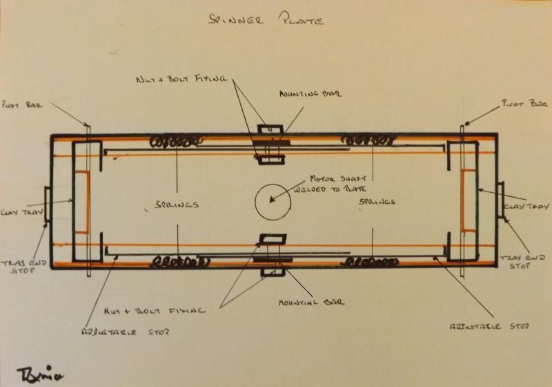
I would firstly like to say I personally have never built one of these launchers but with the help of friend�s memories I am sure we have managed to put together how they were constructed but I am sure there will have to be some trial and error effort invested to get the launcher to function correctly. Now after talking to friends about these launchers I have come to the conclusion they were put together without any thoughts as to safety in operation so the design I have come up with is as safe as I can make it. There are two nuts and bolts in the construction of the spinning plate (for stop adjustment) all the other assembly pieces on the spinner plate must be welded as must the motor shaft to the plate also the tray pivot bar ends should be drilled through and fitted with two split pins at each end about a quarter of an inch apart one as failure backup. These whirly bird launches where always surrounded on all sides by hay bales to stop any chance of a person being injured by a broken clay or a part of the thrower that may come adrift, so it should go without saying no person should be in the hay bale protection area when the launcher is in use. I cannot stress the importance of safety with regard to building or using a launcher of this design if a tray or the top plate or any large part come off when running at full speed it will have the potential to decapitate you at worst and at the very best put you in hospital for some considerable time.
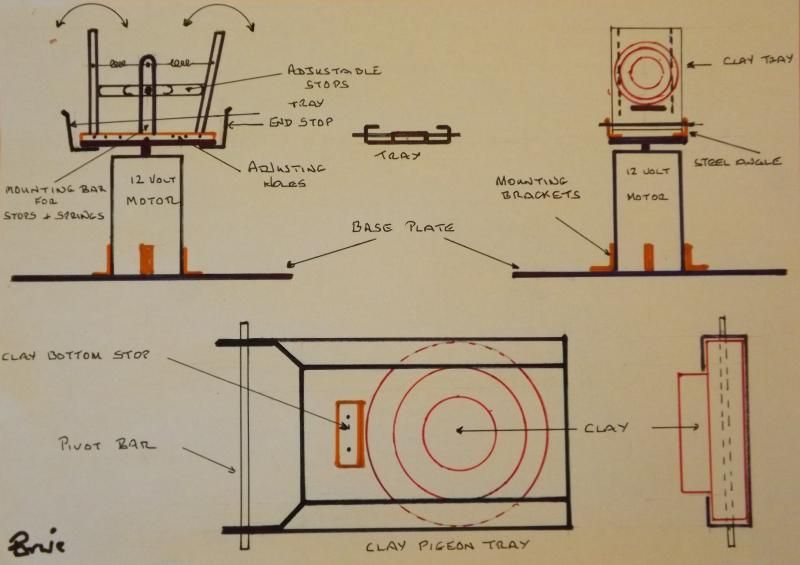
From the drawing you will see that the heart of the Whirly Bird is an automobile starter motor (now builder described the old type Brit motor with a Bendix gear on the shaft which engaged though I should say chewed the teeth on the fly wheel periphery) but like your good selves all the automobiles here now use the pre-engage type motors using a solenoid. So firstly you need to remove the pre-engage solenoid and put it to one side because it can used on a more devilish variant also you need to disable the motor switch that the solenoid acts upon to switch the battery power to the motor, you need to do this so the motor will spin as soon as voltage is applied. Now one thing about starter motors other than they have massive amount of torque but without the load of the engine the terminal no load speed that they can reach is awesome so find yourself a well made heavy duty type with lots of torque. Next the motor is mounted with the motor shaft pointing vertically upwards, I will just say the older motors had a steel casing that enabled four �L� shaped brackets to be welded to the side of the motor for mounting onto a base plate. The construction of modern motors are many and varied so some amount of ingenuity will be required to enable a strong firm motor mounting.
Next a steel plate (the spinner plate), now we think it was approximately 8 inches long by 5 or 6inches wide with a hole at the centre allowing the motor shaft to pass through so it can be welded to the plate for safety reasons it is imperative this union is welded also welded along each of the long sides is a suitable length of steel angle to mount the clay trays and mounting bar for mounting the stop�s and springs etc. which also must be welded. You must make efforts to mount the plate at right angles the shaft to keep vibration to a minimum, and with every subsequent piece you apply to this plate you must do your best to keep it in balanced so it spins as true as possible this is extremely important and cannot be emphasised enough.
The way it works is extremely simple at each end of the spinner plate are the clay launcher trays and a tray stop bar to limit the trays travel to the horizontal this is a safety precaution in the unlikely event that the clay has not left the tray before it reached the true horizontal position, at each side of the spinner plates centre line are the two vertical anchor bars for the adjustable stops and the four tray springs. The inner stop bars are the trays vertical limit stops and you will see that one tray is positioned off centre this off centre position will mean that the clay in that tray will leave the thrower first creating a delay for the second clay. Also on the spinner plate you can see a series of holes so you can move the trays closer to the centre which will also adjust the timing clays leave the trap. One last thing it is the strength of the tray springs that determine how fast the spinner plate has to be traveling before the centrifugal force is enough for the clay to exit the tray and travel through the air.
The more sophisticated versions uses the motors redundant pre-engage solenoid to make a target release on command unit but still utilising adjustable tray angles though they are permanently fixed in use. The electrical release versions let the motor reach terminal speed before the target is released increasing its flight speed, also the electrical control circuitry is arranged to disconnect the voltage supplied to the motor as soon as the target release button is pressed.
And finally as you will see I am not the world�s finest technical drawing exponent also I must admit I started to lose the will to live when switching on my scanner it immediately decided to take up smoking. So I photographed the drawings, also they are not working drawings just overview drawings though I am sure if you really want to construct one of these devilish things there is sufficient information for you to do so.